5. Michelson Interferometer
Module
Wave Optics · Interferometry
Try it live
Explore this on the interactive simulator with real-time sliders and graphs: 🔬 Launch in Simulator
Aim
To study the circular fringe pattern produced by a Michelson interferometer and to use fringe counting to measure the displacement of a movable mirror.
Theoretical Background
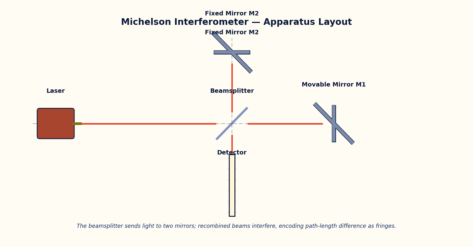
A Michelson interferometer splits a coherent beam at a 50:50 beamsplitter into two arms, each terminated by a mirror. One mirror (M1) is mounted on a precision translation stage; the other (M2) is fixed. The two beams recombine at the beamsplitter and interfere, producing a pattern of circular fringes (in the collimated-beam, equal-inclination configuration) centred on the optical axis.
When the movable mirror M1 is displaced by ΔL, the round-trip path in that arm changes by 2ΔL, changing the optical path difference between the two arms by the same amount. Each time this path difference changes by exactly one wavelength λ, one complete ring collapses into (or emerges from) the centre of the pattern — i.e. the fringe order at the centre shifts by exactly 1.
By counting the number of fringes Δm that cross the centre while moving the mirror a known (or unknown) distance, the mirror displacement can be measured to a small fraction of a wavelength: ΔL = (Δm · λ)/2. This is the operating principle of the original Michelson–Morley experiment and of modern laser interferometric displacement and vibration sensors.
Governing Formulas
Optical path difference:
Fringe order shift:
Mirror displacement from fringe count:
Simulator Controls
| Control | Symbol | Range | Unit |
|---|---|---|---|
| Movable mirror displacement | ΔL | 0 – 3000 | nm |
| Wavelength | λ | 400 – 700 | nm |
Procedure
- Set λ to a fixed value (e.g. 633 nm, He-Ne) and record the initial fringe order reading at ΔL = 0.
- Increase ΔL in small, regular steps and record the optical path difference (2ΔL) and the fringe-order shift Δm displayed at each step.
- Repeat the run for a second wavelength and compare the number of fringes crossing the centre for the same mechanical displacement.
- Plot Δm against ΔL and verify the expected straight-line relationship of slope 2/λ.
Observation Table
Table: Fringe-order shift as a function of mirror displacement
| S. No. | ΔL (nm) | λ (nm) | OPD = 2ΔL (nm) | Δm = 2ΔL/λ (observed) |
|---|---|---|---|---|
| 1 | ||||
| 2 | ||||
| 3 | ||||
| 4 | ||||
| 5 | ||||
| 6 | ||||
| 7 | ||||
| 8 |
Graph
Plot Fringe order shift Δm (y-axis) against Mirror displacement ΔL (nm) (x-axis).
Expected trend: a straight line through the origin of slope 2/λ.
Δm vs ΔL used to extract an experimental wavelength
Calculation
- From the slope of the Δm vs ΔL graph, compute λ_experimental = 2/slope.
- Compare λ_experimental with the λ set on the simulator and compute the percentage error.
Result
Table: Wavelength determination by fringe counting
| λ set (nm) | λ from slope (nm) | % error |
|---|---|---|
| 1 | ||
| 2 | ||
| 3 |
Maximum Permissible Error
ΔL = Δm·λ/2. The dominant error is usually miscounting fringes by ±1 near the start/end of a sweep, contributing ±λ/2 directly; the source's own spectral uncertainty adds a smaller relative term.
Precautions
- Move the mirror in one direction only during a counting run to avoid ambiguity from backlash.
- Choose a step size small enough that no fringe crossing is missed, especially at shorter wavelengths.
Self-Check Quiz
1. Moving mirror M1 by ΔL changes the round-trip path in that arm by:
- A) ΔL
- B) 2ΔL
- C) ΔL/2
- D) 4ΔL
Answer: B — Light travels to M1 and back, so a mirror displacement ΔL changes the path length in that arm by 2ΔL — this is why the OPD = 2ΔL.
2. One complete ring collapses into (or emerges from) the centre of the pattern each time the OPD changes by:
- A) λ/4
- B) λ/2
- C) Exactly one wavelength λ
- D) 2λ
Answer: C — Each time the optical path difference changes by exactly one wavelength, the fringe order at the centre shifts by 1, i.e. one ring appears or disappears.
3. If you count Δm = 500 fringes while moving the mirror, using λ = 632.8 nm, the mirror displacement ΔL is closest to:
- A) 0.158 mm
- B) 0.316 mm
- C) 0.633 mm
- D) 1.266 mm
Answer: A — ΔL = Δm·λ/2 = 500 × 632.8 nm / 2 = 158,200 nm ≈ 0.158 mm.
4. A Michelson interferometer is fundamentally useful for precision metrology because it converts:
- A) Light intensity into colour
- B) A tiny mechanical displacement into an easily-countable number of fringes
- C) Coherent light into incoherent light
- D) Wavelength into polarization angle
Answer: B — Counting fringes as a mirror moves gives a displacement measurement accurate to a fraction of a wavelength — the basis of interferometric metrology.
Viva-Voce Questions
- Why does the fringe pattern in a Michelson interferometer appear as concentric circles rather than straight lines?
- How is this instrument related historically to the Michelson–Morley experiment on the ether?
- Why does displacing the movable mirror by a distance λ/2 shift the fringe pattern by exactly one fringe?
- What is the role of the beamsplitter in this interferometer, and why must it be set at 45° to the incident beam?
- How can a Michelson interferometer be used to measure the wavelength of an unknown monochromatic source?
- What change would you expect in the fringe pattern if a thin glass plate were inserted in one arm of the interferometer?
- Why is mechanical and thermal stability important while performing this experiment?