3. Polarization & Malus's Law
Module
Wave Optics · Module 3
Try it live
Explore this on the interactive simulator with real-time sliders and graphs: 🔬 Launch in Simulator
Aim
To verify Malus's Law by measuring the transmitted intensity through an analyzer as a function of the angle between the polarizer and analyzer transmission axes.
Theoretical Background
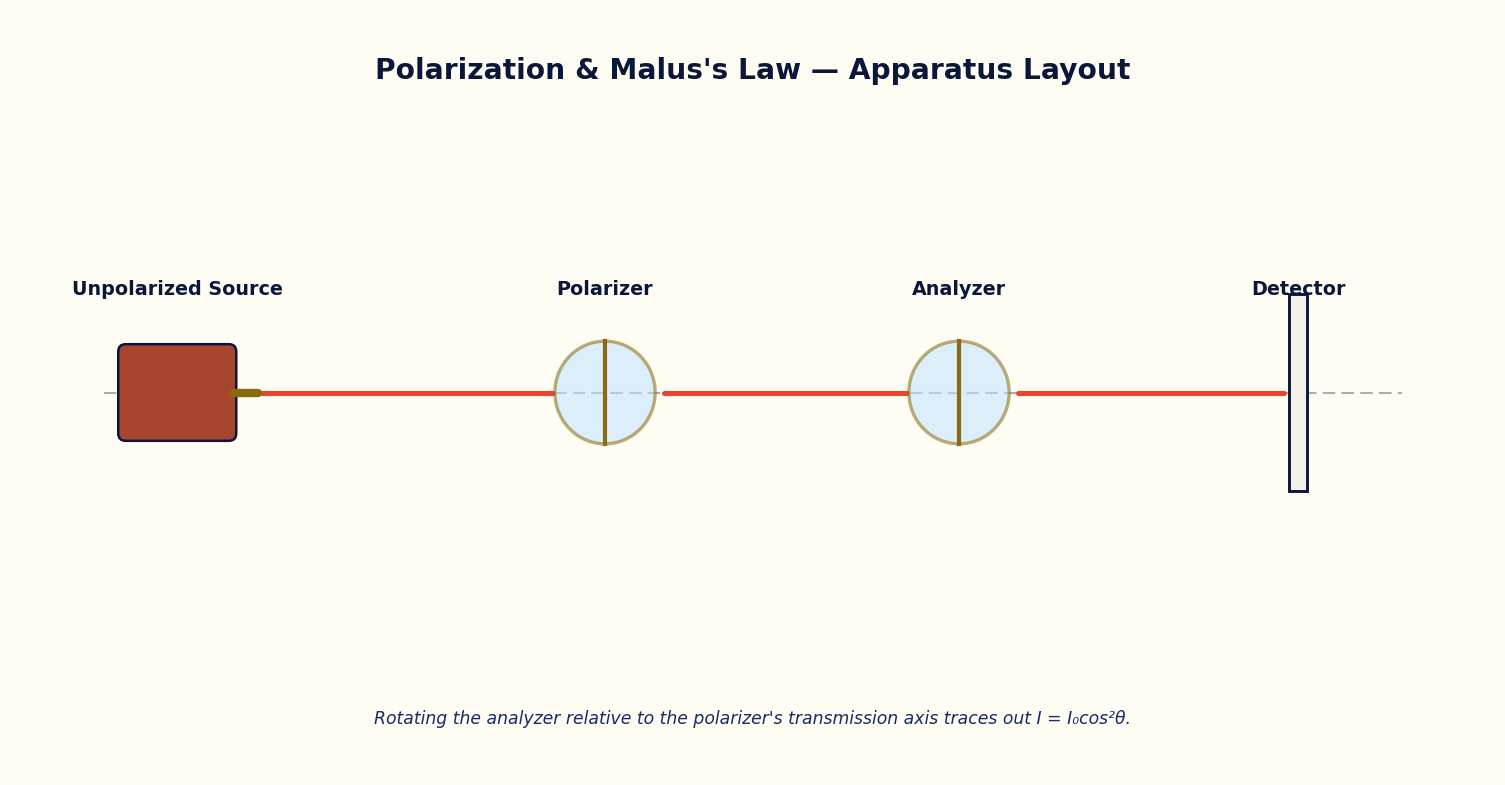
Ordinary light contains electric field oscillations in all directions transverse to the propagation direction. A polarizer transmits only the component of the field parallel to its transmission axis, producing linearly polarized light of amplitude E0. When this polarized beam is passed through a second polarizer (the analyzer) whose transmission axis makes an angle θ with the first, only the component E0 cosθ is transmitted.
Since intensity is proportional to the square of the field amplitude, the transmitted intensity follows Malus's Law, I = I0 cos²θ, where I0 is the intensity transmitted when θ = 0. At θ = 90° (crossed polarizers) the transmitted intensity theoretically falls to zero.
This principle underlies polarimeters, photoelastic stress analysis, LCD displays, and the design of quarter-wave and half-wave plates used to generate circularly and elliptically polarized light.
Governing Formulas
Malus's Law:
Simulator Controls
| Control | Symbol | Range | Unit |
|---|---|---|---|
| Analyzer angle | θ | 0 – 180 | ° |
| Incident intensity | I0 | 10 – 100 | % |
Procedure
- Set the incident intensity I0 to a convenient fixed value (e.g. 100%).
- Vary the analyzer angle θ in steps of 15° from 0° to 180° and record the transmitted intensity readout at each step.
- Repeat the run for a second value of I0 to confirm that the cos²θ dependence is independent of the absolute intensity.
- Plot I(θ) against θ and separately I(θ) against cos²θ.
Observation Table
Table: Transmitted intensity versus analyzer angle (θ = 0° to 180° in steps of 15°)
| S. No. | θ (°) | cos²θ | I observed (%) | I0 cos²θ calculated (%) |
|---|---|---|---|---|
| 1 | ||||
| 2 | ||||
| 3 | ||||
| 4 | ||||
| 5 | ||||
| 6 | ||||
| 7 | ||||
| 8 | ||||
| 9 | ||||
| 10 | ||||
| 11 | ||||
| 12 | ||||
| 13 |
Graph
Plot Transmitted intensity I (%) (y-axis) against cos²θ (x-axis).
Expected trend: a straight line through the origin of slope I0.
I vs cos²θ — a straight line confirms Malus's Law
Calculation
- Compute cos²θ for every recorded angle.
- Plot I against cos²θ; the slope of the best-fit straight line gives the experimental I0.
- Compare the graph-derived I0 with the value set on the simulator and compute the percentage deviation.
Result
Table: Verification of Malus's Law
| I0 set (%) | I0 from graph slope (%) | % deviation |
|---|---|---|
| 1 | ||
| 2 | ||
| 3 |
Maximum Permissible Error
I = I₀cos²θ, so d(ln I) = d(ln I₀) − 2 tanθ·dθ; the angle term grows rapidly as θ → 90°, so avoid taking your reading very close to the crossed-polarizer position.
Precautions
- Take enough angle readings near θ = 90° since the intensity changes most rapidly there.
- Always plot I against cos²θ (not θ) to obtain a straight line for slope analysis.
Self-Check Quiz
1. At θ = 45° between polarizer and analyzer, what fraction of I0 is transmitted?
- A) 100%
- B) 70.7%
- C) 50%
- D) 0%
Answer: C — I = I0 cos²(45°) = I0 × 0.5 = 50% of I0.
2. At what angle θ does Malus's Law predict zero transmitted intensity?
- A) 0°
- B) 45°
- C) 60°
- D) 90°
Answer: D — cos²(90°) = 0 — this is the 'crossed polarizers' condition.
3. Why is intensity proportional to cos²θ and not cosθ?
- A) Intensity is proportional to the square of the field amplitude, and only the E0 cosθ component of the field is transmitted
- B) It's an empirical fit with no physical reason
- C) Because θ is always small
- D) Because two polarizers are used instead of one
Answer: A — Only the field component E0 cosθ passes the analyzer; since intensity ∝ (field)², I ∝ (E0 cosθ)² = I0 cos²θ.
4. Ordinary (unpolarized) light passed through a single ideal polarizer emerges with intensity:
- A) Zero
- B) The full incident intensity
- C) Half the incident intensity (on average)
- D) I0 cos²θ, same as after the analyzer
Answer: C — Unpolarized light has field oscillations equally distributed in all transverse directions, so on average a single ideal polarizer transmits half the incident intensity — this I0 is then used as the reference for Malus's Law at the second polarizer.
Viva-Voce Questions
- Why does natural (unpolarized) light not show a cos²θ dependence when passed through a single polarizer alone?
- What is the difference between a polarizer and an analyzer in this experimental arrangement?
- What happens to the transmitted intensity when the analyzer is rotated to 90° with respect to the polarizer?
- Why does unpolarized light lose exactly half its intensity after passing through the first (ideal) polarizer?
- Distinguish between polarization by selective absorption (as in a Polaroid) and polarization by reflection.
- At what angle between polarizer and analyzer axes is the rate of change of transmitted intensity greatest?
- How would you experimentally verify that a given beam of light is completely unpolarized?