1. Young's Double-Slit Interference
Module
Wave Optics · Module 1
Try it live
Explore this on the interactive simulator with real-time sliders and graphs: 🔬 Launch in Simulator
Aim
To study the interference pattern produced by two coherent slits and to determine the fringe width for a given wavelength, slit separation and screen distance.
Theoretical Background
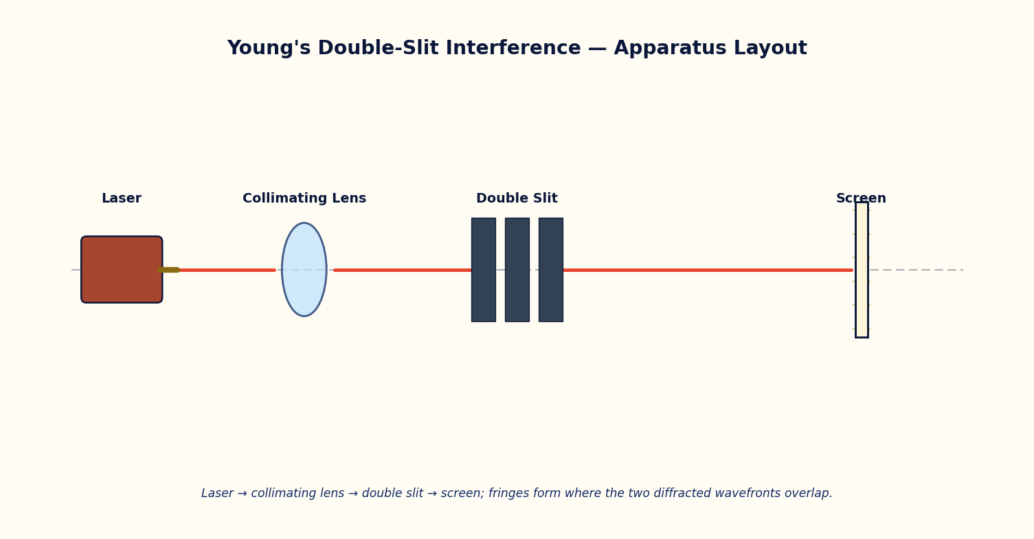
When a monochromatic wavefront falls on two narrow, closely spaced slits S1 and S2, each slit acts as a secondary source of coherent spherical wavelets (Huygens' principle). Because the two wavelets originate from the same primary wavefront, they maintain a constant phase relationship and can interfere both constructively and destructively when they overlap on a screen placed at a distance D from the slits.
At a point P on the screen at a perpendicular distance y from the central axis, the path difference between the two wavelets is approximately delta = d*y/D, where d is the slit separation. Constructive interference (a bright fringe) occurs when this path difference equals an integer number of wavelengths, and destructive interference (a dark fringe) occurs when it equals a half-integer number of wavelengths.
The linear spacing between two consecutive bright (or dark) fringes is called the fringe width, beta. It increases with wavelength and screen distance, and decreases with slit separation. The overall two-slit interference pattern is also modulated by a single-slit diffraction envelope determined by the individual slit width a; slits that are too wide suppress the outer interference fringes.
This experiment is the historical proof of the wave nature of light (Thomas Young, 1801) and underlies the operation of Fresnel's biprism and Lloyd's mirror arrangements used elsewhere in the optics curriculum (BAS101 Unit 1).
Governing Formulas
Path difference at P:
Condition for bright fringe (order n):
Condition for dark fringe:
Fringe width:
Simulator Controls
| Control | Symbol | Range | Unit |
|---|---|---|---|
| Wavelength | λ | 400 – 700 | nm |
| Slit separation | d | 20 – 200 | μm |
| Screen distance | D | 20 – 200 | cm |
| Slit width | a | 5 – 60 | μm |
Procedure
- Launch the Young's Double-Slit panel and note the default wavelength, slit separation and screen distance.
- Keeping d and D fixed, vary the wavelength λ across the visible range and record the resulting fringe width shown on the readout.
- Reset λ to a fixed value; vary the slit separation d over its full range and tabulate the fringe width for each setting.
- Reset d; vary the screen distance D over its full range and tabulate the fringe width.
- For each of the three runs, plot the measured beta against the varied quantity and compare with the theoretical straight-line/inverse relationship.
- Reduce the slit width a to a very small value and observe how the diffraction envelope widens, allowing more interference fringes to appear within the central maximum.
Observation Table
Table: Variation of fringe width with wavelength (d, D held constant)
| S. No. | λ (nm) | d (μm) | D (cm) | Fringe width β (mm) — observed | β = λD/d (mm) — calculated |
|---|---|---|---|---|---|
| 1 | |||||
| 2 | |||||
| 3 | |||||
| 4 | |||||
| 5 | |||||
| 6 |
Graph
Plot Fringe width β (mm) (y-axis) against Wavelength λ (nm) (x-axis).
Expected trend: a straight line through the origin (β ∝ λ).
β vs λ, and separately β vs 1/d, both expected to be straight lines through the origin
Calculation
- For each row, compute β_theory = λD/d using the values of λ, D and d used in that trial.
- Compare β_theory with the β_observed read from the simulator readout and compute the percentage deviation.
- From the slope of the β vs λ graph (at fixed d, D), estimate the effective ratio D/d and compare with the set values.
Result
Table: Summary of fringe-width dependence
| Quantity varied | Slope from graph | Expected relation | % deviation |
|---|---|---|---|
| 1 | |||
| 2 | |||
| 3 |
Maximum Permissible Error
β = λD/d is a simple product/quotient of three measured quantities, so the maximum fractional error is the sum of the fractional errors (least count / measured value) of each.
Precautions
- Change only one control at a time so that the dependence being tested remains unambiguous.
- Record the readout values to the precision displayed; do not round prematurely.
- Note whether the diffraction envelope (slit width a) is suppressing outer fringes before concluding a trend from few visible fringes.
Self-Check Quiz
1. If the slit separation d is halved while D and λ stay the same, the fringe width β:
- A) Halves
- B) Doubles
- C) Stays the same
- D) Quadruples
Answer: B — β = λD/d, so β is inversely proportional to d — halving d doubles β.
2. At the exact centre of the screen (y = 0), the path difference Δ is:
- A) λ/2
- B) λ/4
- C) Zero
- D) Undefined
Answer: C — At y = 0 the two paths S1P and S2P are equal, so Δ = dy/D = 0, giving a bright central fringe (zeroth order).
3. Why must S1 and S2 be illuminated by the same primary wavefront rather than two separate independent sources?
- A) To increase the total intensity
- B) To ensure a constant, predictable phase relationship (coherence) between the two wavelets
- C) To make the slits narrower
- D) It doesn't matter, any two sources work
Answer: B — Two independent sources have randomly fluctuating relative phase, so any interference pattern washes out instantly — coherence is essential.
4. A dark fringe occurs when the path difference equals:
- A) An integer number of wavelengths
- B) Zero
- C) A half-integer number of wavelengths
- D) The slit separation d
Answer: C — Δ = (n + 1/2)λ gives destructive interference — the two wavelets arrive exactly out of phase.
Viva-Voce Questions
- Why must the two sources be coherent for a stationary interference pattern to be observed?
- What happens to the fringe width if the entire apparatus is immersed in a medium of refractive index n?
- Distinguish between the interference pattern and the diffraction envelope that modulates it.
- How would the fringe width change if the wavelength of the laser source were doubled, all else unchanged?
- What happens to the fringe pattern if the separation between the two slits, d, is increased while D is kept fixed?
- Why is a laser preferred over an ordinary sodium lamp for obtaining a clean, high-contrast fringe pattern in this setup?
- What would you observe on the screen if one of the two slits were completely blocked?