2. Single-, Double- and N-Slit Diffraction
Module
Wave Optics · Module 2
Try it live
Explore this on the interactive simulator with real-time sliders and graphs: 🔬 Launch in Simulator
Aim
To observe how the diffraction pattern evolves from a single slit through a double slit to an N-slit grating, and to verify the grating equation and resolving power relation.
Theoretical Background
A single slit of width a produces a diffraction pattern with a broad central maximum flanked by weaker secondary maxima; the first minima occur where a*sinθ = λ. When a second identical slit is added at spacing (a+b), the two-slit interference term multiplies the single-slit diffraction envelope, giving the familiar Young's-fringe-inside-an-envelope pattern.
Extending this to N equally spaced slits (a diffraction grating) produces sharp principal maxima at angles satisfying (a+b) sinθ = nλ, with N-2 much weaker secondary maxima appearing between consecutive principal maxima. As N increases, the principal maxima become progressively narrower and more intense — the basis of the diffraction-grating spectrometer.
The ability of a grating to separate two closely spaced wavelengths is quantified by its resolving power R = λ/Δλ = nN, where n is the diffraction order used. A larger number of illuminated slits (or grooves) therefore gives finer spectral resolution for a given order.
Governing Formulas
Single-slit minima:
N-slit (grating) principal maxima:
Resolving power:
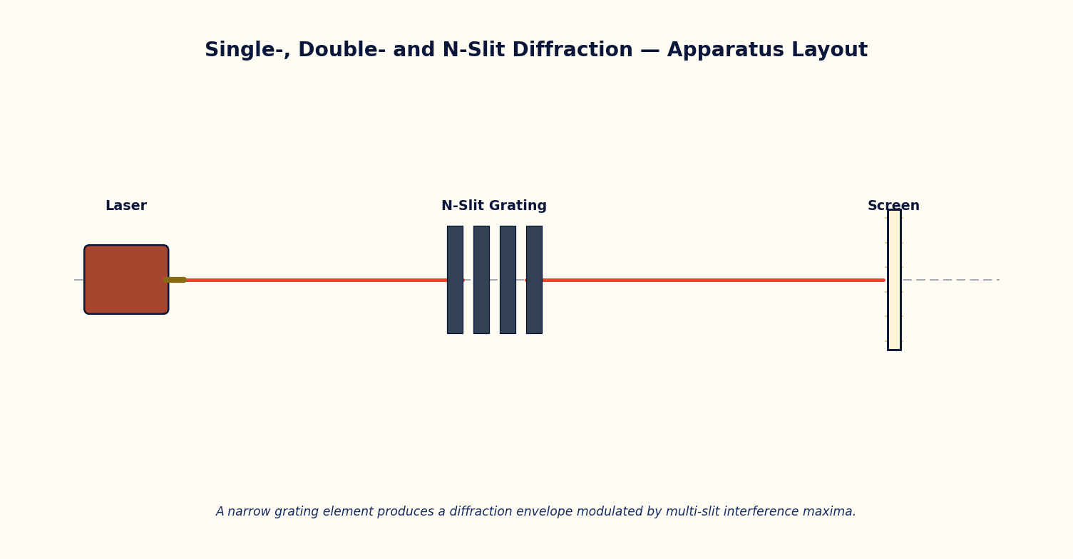
Simulator Controls
| Control | Symbol | Range | Unit |
|---|---|---|---|
| Number of slits | N | 1 – 12 | — |
| Slit width | a | 4 – 40 | μm |
| Slit spacing | a+b | 20 – 150 | μm |
| Wavelength | λ | 400 – 700 | nm |
Procedure
- Set N = 1 and record the single-slit diffraction pattern; note the angular position of the first minimum for at least three slit widths a.
- Set N = 2 and note how the double-slit interference fringes appear inside the same diffraction envelope.
- Increase N progressively (2, 4, 6, 8, 12) at fixed a and (a+b); for each N record the apparent sharpness/width of the principal maxima and the computed resolving power R = nN.
- For a fixed N ≥ 4, vary the wavelength λ and tabulate the angular shift of the first-order principal maximum.
- Plot R against N and verify the expected linear relationship.
Observation Table
Table: Resolving power as a function of number of illuminated slits N
| S. No. | N | a (μm) | (a+b) (μm) | λ (nm) | R = nN (n=1) |
|---|---|---|---|---|---|
| 1 | |||||
| 2 | |||||
| 3 | |||||
| 4 | |||||
| 5 | |||||
| 6 |
Graph
Plot Resolving power R (y-axis) against Number of slits N (x-axis).
Expected trend: a straight line through the origin (R = nN).
R vs N at fixed diffraction order n = 1
Calculation
- For each row compute the theoretical first-order angle from (a+b) sinθ = λ and compare with the simulator's rendered maximum position.
- Compute R = nN for each N and plot against N; confirm a straight line of slope n through the origin.
Result
Table: Resolving power verification
| N | R (calculated) | R (from slope of graph) | % deviation |
|---|---|---|---|
| 1 | |||
| 2 | |||
| 3 |
Maximum Permissible Error
From (a+b) sinθ = nλ, differentiating gives a cotθ term for the angle uncertainty in addition to the wavelength's fractional error.
Precautions
- Keep the diffraction order under consideration (usually n = 1) fixed when comparing resolving powers across different N.
- Distinguish clearly between the diffraction envelope minima (single slit) and the interference principal maxima (multi-slit).
Self-Check Quiz
1. For a single slit of width a, the first diffraction minimum occurs when:
- A) a sinθ = λ/2
- B) a sinθ = λ
- C) a sinθ = 2λ
- D) sinθ = a/λ
Answer: B — The single-slit minima condition is a sinθ = mλ, so the first minimum (m = 1) is at a sinθ = λ.
2. As the number of slits N in a grating increases (spacing fixed), the principal maxima become:
- A) Broader and dimmer
- B) Narrower and more intense
- C) Unchanged
- D) They disappear
Answer: B — More illuminated slits sharpen the principal maxima and increase their peak intensity — this is exactly why grating spectrometers use many slits/grooves.
3. The resolving power R = λ/Δλ = nN tells you that, for a fixed diffraction order n, resolving power improves by:
- A) Increasing the number of illuminated slits N
- B) Increasing the slit width a
- C) Decreasing the wavelength only
- D) Reducing N
Answer: A — R is directly proportional to N at fixed order n, so illuminating more slits/grooves of the grating improves its ability to separate close wavelengths.
4. Which pattern do you get by multiplying the single-slit diffraction envelope by the two-slit interference term?
- A) A pure single-slit pattern
- B) A pure N-slit grating pattern
- C) Young's fringes modulated inside a single-slit diffraction envelope
- D) A completely uniform intensity
Answer: C — The classic double-slit pattern is the fine Young's fringes (from two-slit interference) riding inside the broader single-slit diffraction envelope.
Viva-Voce Questions
- Why do secondary maxima become negligible once N is large?
- How does the resolving power of a grating relate to the total number of illuminated grooves rather than the groove spacing alone?
- How does the width of the central diffraction maximum change if the slit width a is reduced?
- Why are the secondary maxima in single-slit diffraction much weaker than the central maximum?
- What is the physical difference between the diffraction envelope and the interference fringes seen in a double-slit pattern?
- How does increasing the number of slits N change the sharpness of the principal maxima in grating diffraction?
- Define the resolving power of a diffraction grating and state the factors it depends on.