Faraday's Law of Electromagnetic Induction
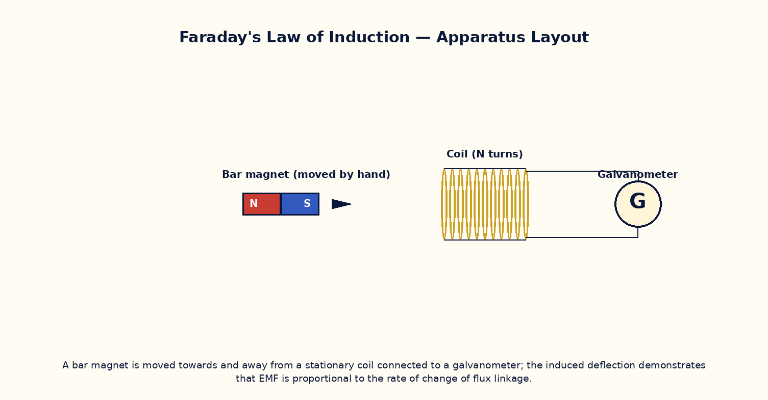
Aim
To verify Faraday's law of electromagnetic induction by studying the EMF induced in a coil due to a changing magnetic flux, and to confirm Lenz's law for the direction of the induced current.
Theoretical Background
Faraday's law states that the EMF induced in a circuit equals the negative rate of change of magnetic flux linkage through it: ε = −N·dΦ_B/dt, where N is the number of turns and Φ_B = ∫B·dA is the flux through one turn. The flux can change because the field itself varies in time, because the coil's area or orientation changes, or because a magnet moves relative to the coil. The negative sign is Lenz's law: the induced current always flows in the direction that opposes the change producing it, consistent with energy conservation — work must be done against the induced effects to change the flux, and that work is what appears as electrical energy in the circuit.
Governing Formula
| Symbol | Meaning |
|---|---|
| ε | induced EMF (V) |
| N | number of turns in the coil |
| Φ_B | magnetic flux linking one turn (Wb) |
| t | time (s) |
Interactive Controls
Launch the simulator and use the following controls on the Faraday's Law of Electromagnetic Induction panel:
| Control | Symbol | Range | Default |
|---|---|---|---|
| Number of turns | N | 10–500 | 100 |
| Magnet approach speed | v | 1–50 cm/s | 10 cm/s |
| Peak field of the magnet | B_max | 5–100 mT | 30 mT |
| Coil cross-sectional area | A | 5–50 cm² | 20 cm² |
Procedure
- Move the magnet toward the coil at a fixed speed and record the induced EMF pulse on the virtual oscilloscope; note its sign.
- Repeat, withdrawing the magnet at the same speed, and note the induced EMF reverses sign.
- Double the approach speed and verify the peak EMF approximately doubles (steeper dB/dt).
- Increase the number of turns N and verify the induced EMF scales proportionally.
- Hold the magnet stationary inside the coil and confirm the induced EMF is exactly zero (no change in flux).
- Use the induced current's direction (read from the galvanometer deflection) to verify Lenz's law by checking it opposes the magnet's approach/withdrawal.
Observation Table
| S. No. | Turns N | Magnet speed v (cm/s) | Peak field B_max (mT) | Peak EMF ε (mV) | Direction (approach/withdraw) | |---|---|---|---|---|---|| | | | | | | | | | | | | | | | | | | | | | | | | | | | | | | | | | | |
Graph
Induced EMF vs Time (magnet passing through coil) — bipolar pulse: + then − (or vice versa)
Calculations
Use the governing formula above with your tabulated observations to compute the required result for each row. Show at least one complete sample calculation with units.
Result
| Case | EMF observed | EMF predicted (−N dΦ/dt) | Lenz's law direction verified? | |---|---|---|---|| | | | | |
Precautions
- Keep the magnet's motion smooth and at a controlled, known speed to get a clean, repeatable EMF pulse.
- Note carefully which face of the magnet (N or S pole) enters the coil first — it fixes the sign of the first EMF lobe.
- Vary only one control (speed, turns, or field strength) at a time to isolate each dependence.
- Remember a stationary magnet inside a stationary coil induces exactly zero EMF, however strong the field.
Maximum Permissible Error
For a magnet swept through at speed v, peak EMF scales with N, the field's peak value and its rate of change (∝ v), so fractional errors add.
Viva-Voce Questions
- State Faraday's law and explain the physical meaning of the negative sign (Lenz's law).
- Why is no EMF induced by a strong but unchanging magnetic field through a stationary coil?
- Derive the motional EMF formula ε = BLv from Faraday's law for a rod sliding on rails in a magnetic field.
- Explain how Lenz's law is a direct consequence of energy conservation.
- How does eddy-current braking make use of Faraday's and Lenz's laws?
- What is self-inductance, and how does it relate to Faraday's law applied to a coil's own changing current?