Force Between Two Parallel Current-Carrying Conductors
Aim
To compute the force per unit length between two long parallel current-carrying wires, verify its dependence on the currents and their separation, and relate it to the SI definition of the ampere.
Theoretical Background
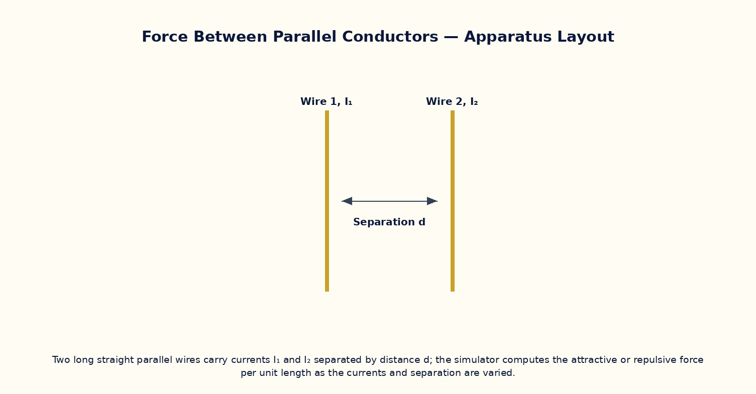
Two long straight parallel wires carrying currents I₁ and I₂, separated by distance d, exert a magnetic force on each other because each wire's field acts on the other's current-carrying charges. The force per unit length is F/L = μ₀I₁I₂/(2πd). Currents in the same direction attract; currents in opposite directions repel — the reverse of the electrostatic case for like/unlike charges. This result was historically used to define the ampere itself: one ampere was (pre-2019) the constant current that, if maintained in each of two straight parallel infinite conductors of negligible cross-section placed one metre apart in vacuum, would produce a force of exactly 2×10⁻⁷ newtons per metre of length between them.
Governing Formula
| Symbol | Meaning |
|---|---|
| F/L | force per unit length between the wires (N/m) |
| I₁, I₂ | currents in the two wires (A) |
| d | separation between the wires (m) |
| μ₀ | permeability of free space |
Interactive Controls
Launch the simulator and use the following controls on the Force Between Two Parallel Current-Carrying Conductors panel:
| Control | Symbol | Range | Default |
|---|---|---|---|
| Current in wire 1 | I₁ | 0.5–20 A | 5 A |
| Current in wire 2 | I₂ | 0.5–20 A | 5 A |
| Separation | d | 1–30 cm | 5 cm |
| Relative direction (0=same, 1=opposite) | dir | 0–1 | 0 |
Procedure
- Set both currents in the same direction and vary the separation d; plot F/L vs 1/d and verify linearity.
- Fix d and vary I₁ (keeping I₂ fixed); verify F/L ∝ I₁.
- Reverse the direction of I₂ and note the force changes from attractive to repulsive at the same magnitudes.
- Set I₁ = I₂ = 1 A and d = 1 m, and verify the simulator returns F/L = 2×10⁻⁷ N/m, the historical ampere-defining value.
- Increase both currents simultaneously (I₁ = I₂ = I) and verify F/L ∝ I².
- Estimate the force on a 1 m length of two household-wiring conductors carrying typical currents, and comment on why it is not noticeable in daily life.
Observation Table
| S. No. | I₁ (A) | I₂ (A) | Separation d (cm) | Direction (same/opp.) | Force/length (×10⁻⁵ N/m) | |---|---|---|---|---|---|| | | | | | | | | | | | | | | | | | | | | | | | | | | | | | | | | | | |
Graph
Force per Unit Length vs 1/d — straight line through origin
Calculations
Use the governing formula above with your tabulated observations to compute the required result for each row. Show at least one complete sample calculation with units.
Result
| Configuration | F/L measured | F/L predicted | % deviation | |---|---|---|---|| | | | | |
Precautions
- Keep track of current direction carefully — it determines attraction versus repulsion, not just magnitude.
- Vary only one of I₁, I₂, d at a time to isolate each dependence cleanly.
- Remember this is an idealization for infinitely long, thin wires; real finite wires show edge corrections.
- Use consistent SI units throughout when checking the 2×10⁻⁷ N/m reference case.
Maximum Permissible Error
F/L = μ₀I₁I₂/2πd is a product/quotient of three measured quantities.
Viva-Voce Questions
- Derive the force per unit length between two parallel current-carrying wires using the Biot–Savart/Ampere field of one wire acting on the other.
- Why do parallel currents in the same direction attract while antiparallel currents repel?
- Explain the historical (pre-2019) SI definition of the ampere in terms of this force.
- How does the modern (2019 revision) SI definition of the ampere differ, and why was it changed?
- If both currents are doubled, by what factor does the force per unit length change?
- How would you measure this force experimentally using a current balance?