Capacitance of a Parallel-Plate Capacitor (With & Without Dielectric)
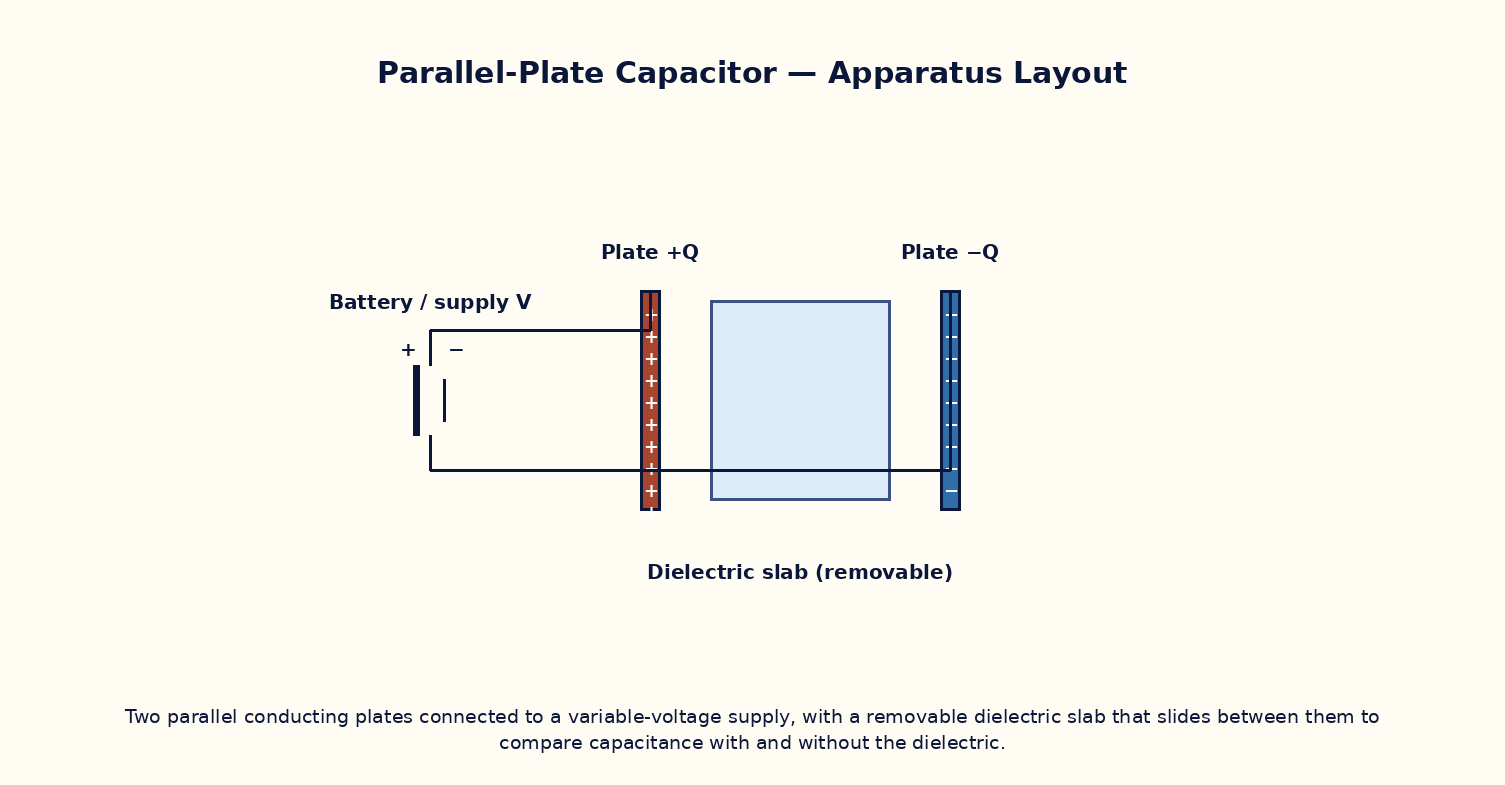
Aim
To study the dependence of a parallel-plate capacitor's capacitance on plate area, plate separation, and an inserted dielectric slab, and to determine the dielectric constant of an unknown material.
Theoretical Background
A parallel-plate capacitor of plate area A separated by distance d in vacuum has capacitance C₀ = ε₀A/d. Filling the gap with a dielectric of relative permittivity εr increases the capacitance to C = εrε₀A/d = εr·C₀, because the bound polarization charges on the dielectric surfaces partially cancel the free-charge field, lowering the potential difference for the same stored charge. If the dielectric slab of thickness t < d only partially fills the gap, the capacitor behaves as two capacitors in series: C = ε₀A / [d − t(1 − 1/εr)]. The stored energy is U = Q²/2C = ½CV², and inserting a dielectric while the plates remain connected to a battery (constant V) increases the stored charge and energy, while at constant charge Q it lowers the voltage and the energy.
Governing Formula
| Symbol | Meaning |
|---|---|
| C | capacitance (F) |
| εr | relative permittivity (dielectric constant) of the medium |
| A | overlap area of the plates (m²) |
| d | plate separation (m) |
Interactive Controls
Launch the simulator and use the following controls on the Capacitance of a Parallel-Plate Capacitor (With & Without Dielectric) panel:
| Control | Symbol | Range | Default |
|---|---|---|---|
| Plate area | A | 50–500 cm² | 200 cm² |
| Plate separation | d | 0.5–10 mm | 2 mm |
| Dielectric constant | εr | 1–80 | 1 |
| Applied voltage | V | 1–100 V | 10 V |
Procedure
- With air between the plates (εr = 1), vary the separation d and plot C vs 1/d to verify the linear relationship.
- Fix d and vary the plate area A; plot C vs A and verify a straight line through the origin.
- Insert dielectric slabs of known εr one at a time (paper ≈ 3, mica ≈ 6, glass ≈ 5–7) fully filling the gap and record the new capacitance; compute εr = C/C₀ for each.
- Use an 'unknown' slab and determine its dielectric constant from the capacitance ratio.
- At fixed Q, insert the dielectric and observe the voltage drop; at fixed V (battery connected), insert the dielectric and observe the increase in stored charge.
- Compute and compare the stored energy U before and after dielectric insertion in both the constant-Q and constant-V cases.
Observation Table
| S. No. | d (mm) | A (cm²) | εr | Capacitance C (pF) | 1/d (mm⁻¹) | |---|---|---|---|---|---|| | | | | | | | | | | | | | | | | | | | | | | | | | | | | | | | | | | |
Graph
Capacitance vs 1/d — straight line through origin
Calculations
Use the governing formula above with your tabulated observations to compute the required result for each row. Show at least one complete sample calculation with units.
Result
| Dielectric material | Measured εr = C/C₀ | Known/standard εr | % deviation | |---|---|---|---|| | | | | |
Precautions
- Ensure the dielectric slab fully and uniformly fills the gap between the plates unless deliberately studying partial filling.
- Keep the plate area and dielectric fixed while varying only the separation, and vice versa.
- Avoid short-circuiting the plates (d → 0); maintain a realistic minimum separation.
- Discharge the capacitor fully before changing the dielectric or geometry to avoid stray residual charge.
Maximum Permissible Error
C = εrε₀A/d is a product/quotient of three measured quantities, so fractional errors add.
Viva-Voce Questions
- Derive the capacitance of a parallel-plate capacitor from first principles using Gauss's law.
- Why does inserting a dielectric always increase the capacitance, never decrease it?
- Distinguish between the behaviour of a dielectric slab at constant charge versus constant voltage.
- Define dielectric constant (relative permittivity) and polarization P; how are they related?
- What is dielectric breakdown, and what determines a material's dielectric strength?
- How would you find the capacitance of a capacitor with the gap only half-filled by a dielectric slab parallel to the plates?