Reflection, Refraction & Brewster's Angle for EM Waves
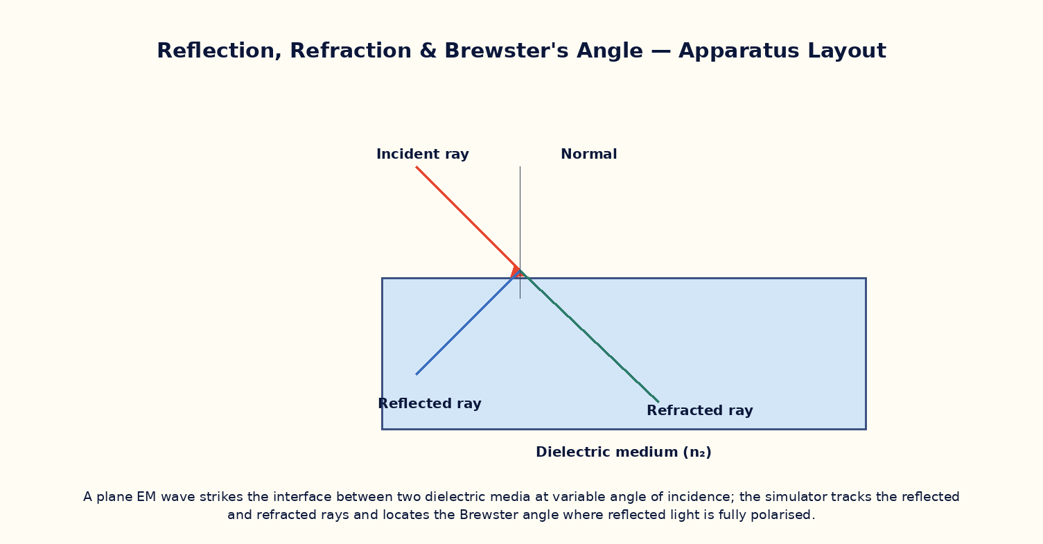
Aim
To study the reflection and transmission of an electromagnetic wave at a dielectric interface using the Fresnel equations, and to locate Brewster's angle at which p-polarized reflection vanishes.
Theoretical Background
When an EM wave meets the planar interface between two dielectric media of refractive indices n₁ and n₂, part of it reflects and part refracts according to Snell's law n₁sinθᵢ = n₂sinθₜ. The fraction reflected depends on polarization and angle of incidence, given by the Fresnel equations. For light polarized with its E-field in the plane of incidence (p-polarization), the reflection coefficient passes through exactly zero at a special angle called Brewster's angle, θ_B = arctan(n₂/n₁), at which the reflected and refracted rays are perpendicular to each other. At this angle, only s-polarized light is reflected, so reflected light off a dielectric surface at Brewster's angle is completely (linearly) polarized — the principle exploited by polarizing sunglasses and by Brewster windows in laser cavities to eliminate reflection losses for one polarization.
Governing Formula
| Symbol | Meaning |
|---|---|
| n₁, n₂ | refractive indices of the incident and transmitting media |
| θᵢ, θₜ | angles of incidence and refraction |
| θ_B | Brewster's angle, at which p-polarized reflectance is zero |
Interactive Controls
Launch the simulator and use the following controls on the Reflection, Refraction & Brewster's Angle for EM Waves panel:
| Control | Symbol | Range | Default |
|---|---|---|---|
| Incident medium index | n₁ | 1–2 | 1 |
| Transmitting medium index | n₂ | 1–2.5 | 1.5 |
| Angle of incidence | θᵢ | 0–89 ° | 30 ° |
| Polarization (0=s, 1=p) | pol | 0–1 | 1 |
Procedure
- For p-polarized light, sweep the angle of incidence from 0° to 89° and plot the reflectance R_p(θᵢ); locate the angle where it drops to zero.
- Compare this angle with the calculated Brewster's angle θ_B = arctan(n₂/n₁) for the chosen n₁, n₂.
- Repeat for s-polarized light and confirm R_s never reaches zero at any angle (no Brewster angle exists for s-polarization).
- At θ = θ_B, verify numerically that the reflected and refracted rays are exactly perpendicular to each other.
- Vary n₂ (keeping n₁ fixed) and verify θ_B shifts accordingly; tabulate θ_B versus n₂/n₁.
- Send unpolarized light (an equal mix of s and p) at θ_B and confirm the reflected beam is purely s-polarized.
Observation Table
| S. No. | n₁ | n₂ | θᵢ (°) | R_p (%) | R_s (%) | |---|---|---|---|---|---|| | | | | | | | | | | | | | | | | | | | | | | | | | | | | | | | | | | |
Graph
Reflectance vs Angle of Incidence — R_p dips to zero at Brewster's angle; R_s does not
Calculations
Use the governing formula above with your tabulated observations to compute the required result for each row. Show at least one complete sample calculation with units.
Result
| n₂/n₁ | Brewster angle (measured) | Brewster angle (arctan n₂/n₁) | % deviation | |---|---|---|---|| | | | | |
Precautions
- Ensure the angle of incidence is measured from the normal to the interface, not from the surface itself.
- Distinguish carefully between s- and p-polarization when reading off reflectance curves — only p shows a Brewster null.
- Keep n₁ < n₂ or n₁ > n₂ clearly in mind, since total internal reflection (a separate phenomenon) only occurs going from denser to rarer medium beyond the critical angle.
- Use enough angular resolution near the expected Brewster angle to locate the null precisely.
Maximum Permissible Error
Obtained by differentiating θ_B = arctan(n₂/n₁) with respect to the ratio n₂/n₁.
Viva-Voce Questions
- Derive Brewster's angle condition from the Fresnel equation for p-polarized reflectance.
- Why does no Brewster angle exist for s-polarized light?
- Show that at Brewster's angle the reflected and refracted rays are perpendicular.
- How are Brewster windows used inside a laser cavity, and why?
- Distinguish Brewster's angle from the critical angle for total internal reflection.
- How do polarizing sunglasses exploit Brewster-angle reflection from horizontal surfaces like water or roads?