Transmission Lines — Characteristic Impedance, Reflection & VSWR
Aim
To compute the reflection coefficient and voltage standing-wave ratio (VSWR) on a transmission line of characteristic impedance Z₀ terminated in a mismatched load impedance Z_L, and to see how impedance matching minimises reflected power.
Theoretical Background
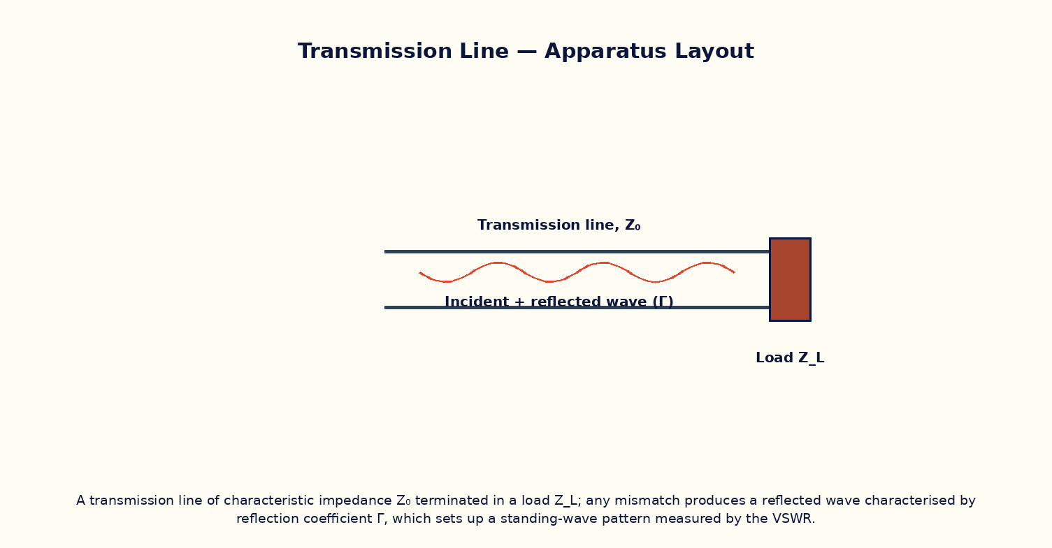
A transmission line — a coaxial cable, a twin-lead, or a printed microstrip trace — has an intrinsic characteristic impedance Z₀ determined by its geometry and the dielectric between its conductors. If the line is terminated in a load whose impedance Z_L differs from Z₀, not all of the incident wave's power can be absorbed by the load; a fraction is reflected back towards the source, described by the (generally complex) reflection coefficient Γ = (Z_L−Z₀)/(Z_L+Z₀). The superposition of the incident and reflected waves sets up a standing-wave pattern along the line, with the ratio of maximum to minimum voltage amplitude called the voltage standing-wave ratio (VSWR). A perfectly matched load (Z_L = Z₀) gives Γ = 0 and VSWR = 1 (no standing wave, all power delivered to the load), while a short-circuit or open-circuit load gives |Γ| = 1 and an infinite VSWR. Minimising VSWR through careful impedance matching is a central concern in RF and microwave engineering, since a high VSWR both wastes transmitted power and can stress the source.
Governing Formula
| Symbol | Meaning |
|---|---|
| Γ | voltage reflection coefficient (dimensionless) |
| Z₀ | line characteristic impedance (Ω) |
| Z_L | load impedance (Ω, assumed resistive here) |
| VSWR | voltage standing-wave ratio, always ≥ 1 |
Interactive Controls
Launch the simulator and use the following controls on the Transmission Lines — Characteristic Impedance, Reflection & VSWR panel:
| Control | Symbol | Range | Default |
|---|---|---|---|
| Line characteristic impedance | Z₀ | 25–150 Ω | 50 Ω |
| Load impedance (resistive) | Z_L | 5–500 Ω | 75 Ω |
Procedure
- Fix Z₀ = 50 Ω (a standard RF line impedance) and vary Z_L from 5 Ω to 500 Ω, recording Γ and VSWR at each step.
- Plot VSWR versus Z_L and identify the value of Z_L giving the minimum VSWR (it should be Z_L = Z₀).
- Verify that Z_L = 0 (short circuit) and Z_L → ∞ (open circuit) both give |Γ| = 1 and a very large VSWR.
- Repeat for a different line impedance Z₀ (e.g. 75 Ω, as used in cable-TV systems) and note how the optimal load shifts accordingly.
- Discuss what fraction of incident power is reflected for a given Γ (reflected power fraction = |Γ|²), and compute it for one representative mismatch.
Observation Table
| S. No. | Z₀ (Ω) | Z_L (Ω) | Γ | VSWR | Reflected power fraction |Γ|² | |---|---|---|---|---|---|| | | | | | | | | | | | | | | | | | | | | | | | | | | | | | | | | | | |
Graph
VSWR vs load impedance Z_L
Calculations
Use the governing formula above with your tabulated observations to compute the required result for each row. Show at least one complete sample calculation with units.
Result
| Quantity | Z_L giving minimum VSWR | Expected value | % deviation | |---|---|---|---|| | | | | |
Precautions
- Treat the load as purely resistive in this simplified model; a reactive load would give a complex Γ with an additional phase angle.
- Remember VSWR is always ≥ 1, with 1 representing a perfectly matched, reflection-free termination.
- Vary Z_L over a wide enough range to clearly locate the VSWR minimum.
- Do not confuse the characteristic impedance Z₀ (a property of the line itself) with the load impedance Z_L (a property of the termination).
Maximum Permissible Error
VSWR is a nonlinear function of the reflection coefficient Γ, so its propagated uncertainty is best evaluated numerically by perturbing Z₀ and Z_L in turn rather than via one closed-form expression.
Viva-Voce Questions
- Define the reflection coefficient Γ and the voltage standing-wave ratio (VSWR).
- Why does a matched load (Z_L = Z₀) give zero reflection?
- What are the VSWR values for a short-circuit and an open-circuit termination, and why?
- Explain the practical importance of minimising VSWR in an RF transmitter feed line.
- What technique(s) can be used to match a mismatched load to a transmission line?