Magnetic Vector Potential of a Current Loop (Dipole Limit)
Aim
To evaluate the magnetic vector potential A of a small current loop in the far-field (magnetic dipole) approximation, and relate its spatial dependence to the resulting dipole field B = ∇ × A.
Theoretical Background
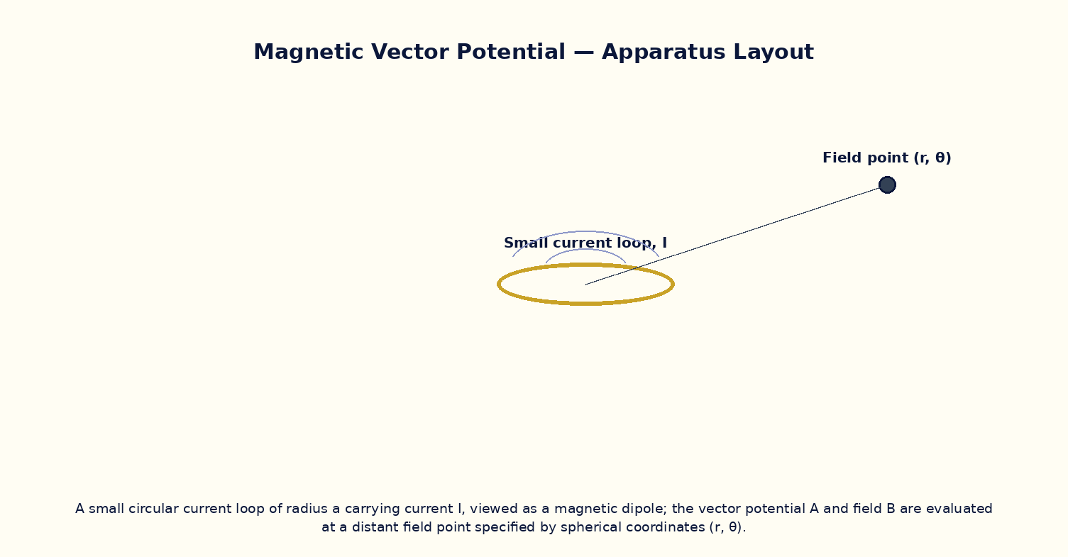
Unlike the scalar electrostatic potential, the magnetic field is more naturally described through a vector potential A, defined by B = ∇ × A, which automatically guarantees ∇·B = 0. For a small planar current loop of radius a carrying current I, viewed from a distance r ≫ a, the vector potential has only an azimuthal component A_φ that falls off as 1/r² and depends on the polar angle θ measured from the loop's axis. This is the magnetic analogue of the electric dipole potential, and the loop's magnetic moment m = I·πa² plays the role that the electric dipole moment p plays in electrostatics. Taking the curl of A_φ reproduces the familiar magnetic dipole field pattern, with field lines emerging from one face of the loop and curving back to enter the other — identical in form to the electric dipole field lines, but without any true magnetic monopoles at the ends.
Governing Formula
| Symbol | Meaning |
|---|---|
| A_φ | azimuthal component of the vector potential (T·m) |
| I | current in the loop (A) |
| a | loop radius (m) |
| r | distance to the field point, r ≫ a |
| θ | polar angle from the loop's axis |
| μ₀ | permeability of free space |
Interactive Controls
Launch the simulator and use the following controls on the Magnetic Vector Potential of a Current Loop (Dipole Limit) panel:
| Control | Symbol | Range | Default |
|---|---|---|---|
| Loop current | I | 0.1–10 A | 2 A |
| Loop radius | a | 0.5–5 cm | 2 cm |
| Field point distance | r | 10–80 cm | 30 cm |
| Polar angle from loop axis | θ | 0–180 deg | 90 deg |
Procedure
- Fix I = 2 A, a = 2 cm and θ = 90° (equatorial plane), and vary r from 10 cm to 80 cm, recording A_φ.
- Plot log A_φ versus log r and verify a slope of −2, confirming the dipole 1/r² fall-off.
- Fix r and vary θ from 0° to 180°, and verify that A_φ follows a sinθ dependence, vanishing on-axis (θ = 0° or 180°).
- Vary the loop current I and confirm A_φ ∝ I.
- Compute the loop's magnetic moment m = Iπa² and compare the measured A_φ(r,90°) with the standard dipole formula A = μ₀m/(4πr²).
Observation Table
| S. No. | r (cm) | θ (deg) | I (A) | A_φ (×10⁻⁶ T·cm) | log r | log A_φ | |---|---|---|---|---|---|---|| | | | | | | | | | | | | | | | | | | | | | | | | | | | | | | | | | | | | | | | |
Graph
log A_φ vs log r (slope method)
Calculations
Use the governing formula above with your tabulated observations to compute the required result for each row. Show at least one complete sample calculation with units.
Result
| Quantity | Slope of log A_φ vs log r | Expected value | % deviation | |---|---|---|---|| | | | | |
Precautions
- Keep r large compared with a to remain within the dipole (far-field) approximation.
- Vary only one of I, a, r, θ at a time while tabulating other quantities.
- Remember A_φ vanishes exactly on the loop's axis (θ = 0°, 180°) — do not mistake this for an error.
- Keep the current direction consistent so that the sign of A_φ has a well-defined meaning.
Maximum Permissible Error
A_φ ∝ Ia²/r² has a and r both squared, each contributing a factor of 2 to the fractional error.
Viva-Voce Questions
- Why is the magnetic field described using a vector potential rather than a scalar potential?
- Define the magnetic dipole moment of a current loop and state its units.
- Show qualitatively how B = ∇ × A reproduces the dipole field pattern from A_φ.
- Compare the r-dependence and angular dependence of A_φ with the electric dipole potential V.
- Why does A_φ vanish on the axis of the loop even though B does not?