Motional EMF & Lenz's Law on a Sliding Rod
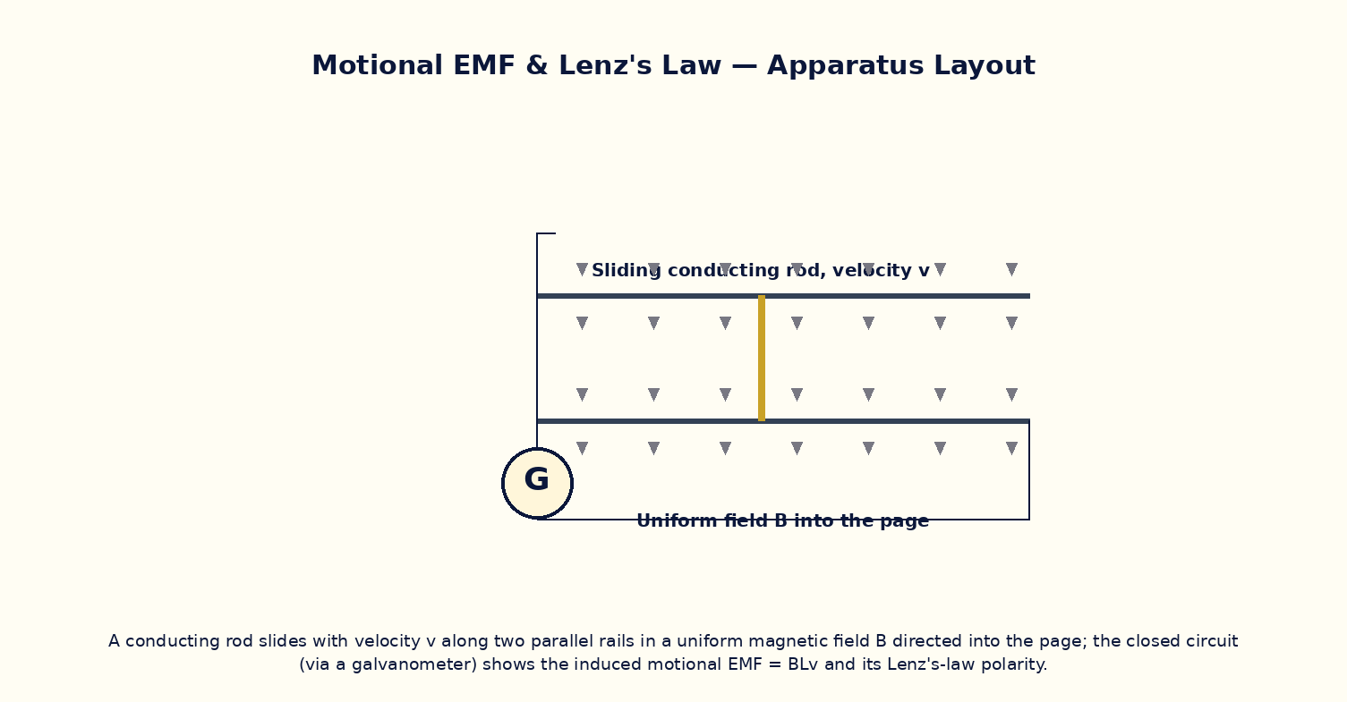
Aim
To study the motional EMF generated by a conducting rod sliding on rails in a uniform magnetic field, verify ε = BLv, and observe the retarding (Lenz's-law) force that opposes the rod's motion when the circuit is closed.
Theoretical Background
When a conducting rod of length L slides with velocity v perpendicular to both its length and a uniform magnetic field B, the free charges in the rod experience a magnetic force qv×B that drives them along the rod, building up an EMF ε = BLv (equivalently derivable from Faraday's law applied to the changing area swept out). If the rod completes a circuit of resistance R, a current I = ε/R flows, and this current in the field experiences a retarding force F = BIL that, by Lenz's law, always opposes the rod's motion — so an external agent must do work against this force to keep the rod moving at constant velocity, and that work exactly equals the electrical energy dissipated in R, consistent with energy conservation.
Governing Formula
| Symbol | Meaning |
|---|---|
| ε | motional EMF (V) |
| B | magnetic field (T) |
| L | rail separation / rod length (m) |
| v | rod velocity (m/s) |
| R | circuit resistance (Ω) |
| F_retard | retarding force on the rod (N) |
Interactive Controls
Launch the simulator and use the following controls on the Motional EMF & Lenz's Law on a Sliding Rod panel:
| Control | Symbol | Range | Default |
|---|---|---|---|
| Magnetic field | B | 10–500 mT | 100 mT |
| Rail separation | L | 5–40 cm | 20 cm |
| Rod velocity | v | 0.1–5 m/s | 1 m/s |
| Circuit resistance | R | 1–50 Ω | 10 Ω |
Procedure
- With the circuit open (infinite R), push the rod at various speeds and confirm the measured EMF matches ε = BLv with no retarding force (no current flows).
- Close the circuit through R and repeat; verify the current I = ε/R and observe the retarding force appearing.
- At fixed v, vary R and verify the retarding force decreases as R increases (F ∝ 1/R).
- At fixed R, vary B and verify the retarding force grows as B² (both the EMF and current scale with B).
- Push the rod at constant velocity against the retarding force and verify the input mechanical power equals the electrical power I²R dissipated in the resistor.
- Reverse the direction of the rod's motion and confirm both the EMF polarity and the retarding force direction reverse consistently with Lenz's law.
Observation Table
| S. No. | B (mT) | L (cm) | v (m/s) | R (Ω) | EMF ε (mV) | Current I (mA) | Retarding force F (×10⁻⁴ N) | |---|---|---|---|---|---|---|---|| | | | | | | | | | | | | | | | | | | | | | | | | | | | | | | | | | | | | | | | | | | | | |
Graph
Motional EMF vs Rod Velocity — straight line through origin, slope = BL
Calculations
Use the governing formula above with your tabulated observations to compute the required result for each row. Show at least one complete sample calculation with units.
Result
| Quantity | Measured value | Predicted value | % deviation | |---|---|---|---|| | | | | |
Precautions
- Ensure the rod remains perpendicular to both the rails and the field direction throughout its motion.
- Keep the rails frictionless and resistanceless in the model so only R limits the current, isolating the physics of interest.
- Vary only one parameter (B, L, v, or R) at a time when tabulating results.
- Note the retarding force acts only while the circuit is closed and current is flowing — an open circuit gives EMF but no force.
Maximum Permissible Error
ε = BLv is a simple product of three measured quantities.
Viva-Voce Questions
- Derive the motional EMF ε = BLv from the magnetic force on free charges in the moving rod.
- Show that the same result follows from Faraday's law applied to the changing enclosed area.
- Why does the rod experience a retarding force only when the circuit is closed?
- Show that the electrical power dissipated equals the mechanical power delivered to keep the rod moving at constant velocity.
- How would the terminal (constant) velocity of a freely falling conducting rod on vertical rails in a field be determined?
- Explain the connection between this experiment and the working principle of an AC generator.