Poynting Vector & Power Flow in a Coaxial Cable
Aim
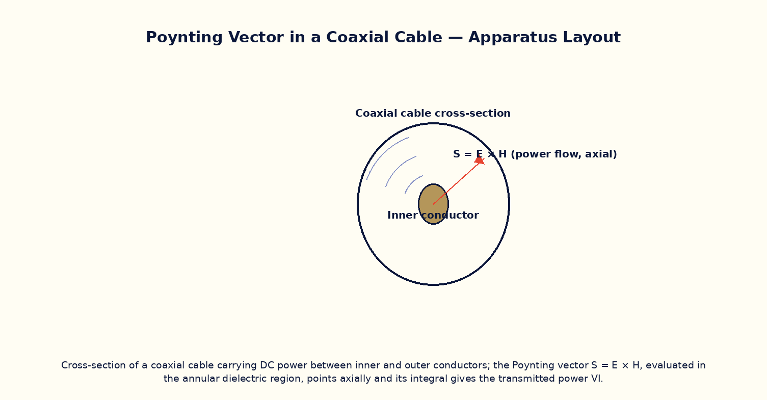
To compute the Poynting vector S = E × H in the dielectric region between the inner and outer conductors of a coaxial cable carrying DC power, and to verify that its integral over the annular cross-section reproduces the transmitted electrical power P = VI.
Theoretical Background
It is a common misconception that electrical power flows through the metal of a wire; in fact, according to Poynting's theorem, electromagnetic power flows through the space (the dielectric or vacuum) surrounding the conductors, described by the Poynting vector S = E × H, with the conductors merely guiding the fields. In a coaxial cable carrying a steady current I at voltage V, the radial electric field E between the inner conductor (radius a) and outer shield (radius b) is set up by the charge on the conductors, while the azimuthal magnetic field H circles the inner conductor according to Ampere's law. Their cross product S = E × H points purely in the axial direction, along the cable, and integrating S over the annular cross-sectional area between a and b reproduces exactly the transmitted power P = VI — a striking and non-obvious confirmation that the field-based picture of energy flow is fully consistent with the familiar circuit-theory result.
Governing Formula
| Symbol | Meaning |
|---|---|
| S(r) | axial Poynting flux at radius r (W/m²) |
| V | voltage between inner and outer conductors (V) |
| I | current carried by the conductors (A) |
| a | inner-conductor radius (m) |
| b | outer-conductor (shield) radius (m) |
| r | field-point radius, a < r < b |
Interactive Controls
Launch the simulator and use the following controls on the Poynting Vector & Power Flow in a Coaxial Cable panel:
| Control | Symbol | Range | Default |
|---|---|---|---|
| Conductor voltage | V | 1–400 V | 100 V |
| Conductor current | I | 0.1–20 A | 5 A |
| Inner-conductor radius | a | 0.3–5 mm | 1 mm |
| Outer-conductor (shield) radius | b | 2–20 mm | 5 mm |
| Field point radius (a<r<b) | r | 1–19 mm | 2.5 mm |
Procedure
- Fix V, I, a, b at their default values and vary the field-point radius r from just above a to just below b, recording S(r) at each step.
- Plot S versus r and verify the expected 1/r² fall-off across the annular gap.
- Numerically (or graphically) integrate S(r) over the annular cross-section (2πr·dr from a to b) and compare the result with the transmitted power P = VI.
- Vary V and I in turn and verify that S(r) at any fixed r scales linearly with each.
- Discuss why S is zero for r < a or r > b (inside the inner conductor or outside the shield).
Observation Table
| S. No. | r (mm) | V (V) | I (A) | S(r) (kW/m²) | |---|---|---|---|---|| | | | | | | | | | | | | | | | | | | | | | | | | | | | | | |
Graph
Poynting flux S vs radius r
Calculations
Use the governing formula above with your tabulated observations to compute the required result for each row. Show at least one complete sample calculation with units.
Result
| Quantity | ∫ S · dA over annulus (→ compare with VI) | Expected value | % deviation | |---|---|---|---|| | | | | |
Precautions
- Only evaluate S(r) strictly between the inner and outer conductors (a < r < b); the field, and hence S, is zero elsewhere in an ideal coaxial cable.
- Keep the current steady (DC) so the simple electrostatic-plus-magnetostatic picture applies without radiation effects.
- Use consistent SI units when integrating S(r) over the annular area to compare with VI.
- Vary only one of V, I, a, b, r at a time while tabulating.
Maximum Permissible Error
S(r) ∝ VI/r² has r squared in the denominator, contributing a factor of 2 to the fractional error.
Viva-Voce Questions
- State Poynting's theorem and define the Poynting vector.
- Explain the common misconception that power flows 'through the wire', and how the Poynting-vector picture corrects it.
- Why does S point purely axially in a coaxial cable carrying steady current?
- Show that integrating S over the annular cross-section reproduces P = VI.
- How would the picture change for an AC (time-varying) signal instead of DC?