Propagation of EM Waves in Dielectric & Conducting Media (Skin Depth)
Aim
To study how the speed, wavelength, and attenuation of an electromagnetic wave change on entering a dielectric or a conducting medium, and to determine the skin depth for a conductor as a function of frequency and conductivity.
Theoretical Background
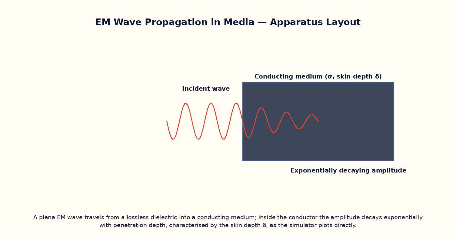
In a lossless dielectric of relative permittivity εr and relative permeability μr, an EM wave travels at reduced speed v = c/n where the refractive index n = √(μrεr), with no attenuation. In a conducting medium of conductivity σ, however, the wave is exponentially attenuated as it propagates because oscillating currents driven by E dissipate energy as heat (Ohmic loss). Its amplitude falls as e^{−z/δ}, where the skin depth δ = √(2/ωμσ) is the distance over which the amplitude drops to 1/e of its surface value. Skin depth decreases with increasing frequency and conductivity, which is why high-frequency currents in a good conductor are confined to a thin surface layer (the 'skin effect'), and why good conductors like metals are excellent reflectors and poor transmitters of high-frequency EM waves.
Governing Formula
| Symbol | Meaning |
|---|---|
| v | wave speed inside the dielectric (m/s) |
| n = √(μrεr) | refractive index |
| δ | skin depth in a conductor (m) |
| ω | angular frequency (rad/s) |
| σ | conductivity (S/m) |
Interactive Controls
Launch the simulator and use the following controls on the Propagation of EM Waves in Dielectric & Conducting Media (Skin Depth) panel:
| Control | Symbol | Range | Default |
|---|---|---|---|
| Relative permittivity (dielectric mode) | εr | 1–10 | 4 |
| Wave frequency | f | 0.1–1000 MHz | 100 MHz |
| Conductivity (conductor mode) | σ | 0.1–60 MS/m | 6 MS/m |
| Medium (0=dielectric, 1=conductor) | mode | 0–1 | 0 |
Procedure
- In dielectric mode, vary εr and verify the wave speed inside falls as v = c/√εr (with μr = 1).
- Verify the wavelength inside the dielectric shrinks by the same factor √εr while the frequency stays fixed (set by the source).
- Switch to conductor mode and vary the frequency; plot δ vs f and verify δ ∝ 1/√f.
- At fixed frequency, vary the conductivity σ and verify δ ∝ 1/√σ.
- Compute the skin depth for copper (σ ≈ 6×10⁷ S/m) at 50 Hz and at 1 GHz, and comment on the enormous difference.
- Estimate, using the skin depth, roughly what thickness of a conducting enclosure is needed to shield against a given frequency (link to the shielding workshop).
Observation Table
| S. No. | Mode | Frequency f (MHz) | εr or σ | Wave speed / Skin depth | Wavelength (dielectric mode) | |---|---|---|---|---|---|| | | | | | | | | | | | | | | | | | | | | | | | | | | | | | | | | | | |
Graph
Skin Depth vs Frequency (log-log) — slope ≈ -1/2
Calculations
Use the governing formula above with your tabulated observations to compute the required result for each row. Show at least one complete sample calculation with units.
Result
| Case | Measured quantity | Theoretical value | % deviation | |---|---|---|---|| | | | | |
Precautions
- Keep μr = 1 (non-magnetic medium) unless specifically studying magnetic conductors, to isolate the effect of εr or σ alone.
- Remember skin depth applies strictly to good conductors (σ/ωε ≫ 1); the formula is not valid for weakly-conducting or dielectric media.
- Use consistent SI units (rad/s for ω, S/m for σ) when checking the numeric value of δ.
- Note the refractive index model here assumes a non-dispersive dielectric; real materials' εr can vary with frequency.
Maximum Permissible Error
δ ∝ 1/√(fσ), so the fractional errors in f and σ are each halved before summing.
Viva-Voce Questions
- Derive the refractive index n = √(μrεr) from the wave equation in a dielectric medium.
- Why does an EM wave attenuate exponentially inside a conductor but not inside an ideal (lossless) dielectric?
- Derive the expression for skin depth starting from the wave equation with a conduction-current term.
- Why are radio antennas and high-frequency circuit traces often silver-plated even though bulk silver is only marginally more conductive than copper?
- How does skin depth explain why AC power transmission cables sometimes use stranded or hollow conductors?
- Relate the concept of skin depth to electromagnetic shielding effectiveness of an enclosure.