Method of Images — Charge Near a Grounded Conducting Plane
Aim
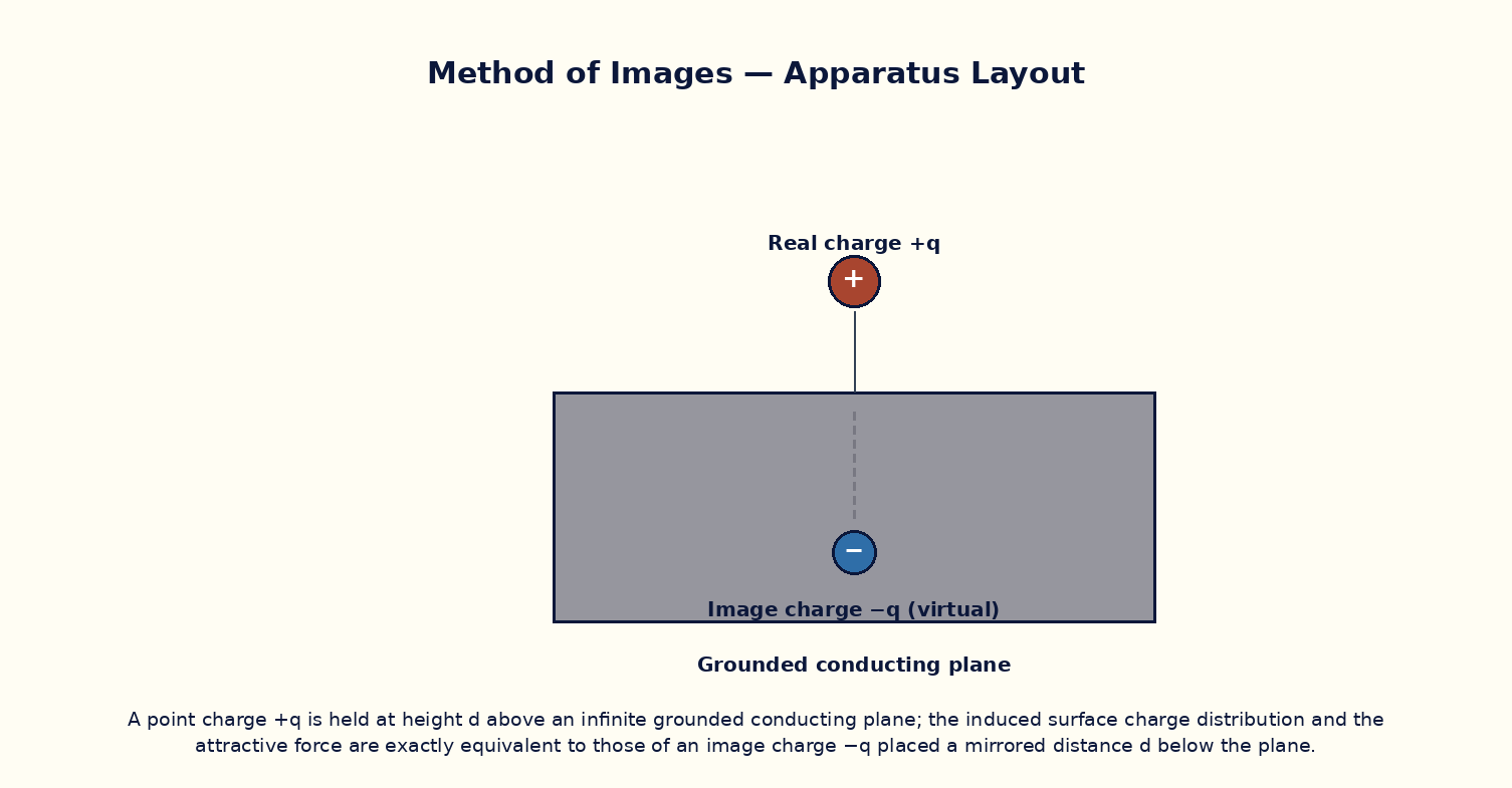
To use the method of images to compute the attractive force between a point charge and a nearby infinite grounded conducting plane, and to show that this force equals that between the real charge and an equal-and-opposite image charge at the mirror position.
Theoretical Background
When a point charge q is placed near a grounded conducting plane, the plane's free electrons rearrange themselves so that the plane remains at zero potential everywhere on its surface. Solving this boundary-value problem directly is difficult, but the method of images gives an elegant shortcut: for the region above the plane, the actual field is identical to the field that would be produced by the real charge q together with a fictitious image charge −q placed at the mirror-image position, with the conducting plane removed entirely. Because both configurations satisfy Laplace's equation above the plane and both give V = 0 on the plane, the uniqueness theorem guarantees they produce the same field in that region. The charge is therefore attracted towards the plane exactly as it would be attracted towards a real charge −q at distance 2d, even though no such charge physically exists — the attraction is due entirely to the induced surface charge on the plane.
Governing Formula
| Symbol | Meaning |
|---|---|
| F | attractive force on the charge towards the plane (N) |
| q | magnitude of the point charge (C) |
| d | perpendicular height of the charge above the plane (m) |
| ε₀ | permittivity of free space |
Interactive Controls
Launch the simulator and use the following controls on the Method of Images — Charge Near a Grounded Conducting Plane panel:
| Control | Symbol | Range | Default |
|---|---|---|---|
| Point charge | q | 1–50 nC | 12 nC |
| Height above the grounded plane | d | 1–20 cm | 5 cm |
Procedure
- Set the charge q = 12 nC and vary the height d from 1 cm to 20 cm in steps of 1 cm, recording the computed attractive force F at each step.
- Plot log F versus log d; the slope should equal −2, confirming the inverse-square dependence on d (equivalently on the image separation 2d).
- Fix d = 5 cm and vary q from 5 nC to 50 nC, verifying that F is proportional to q².
- Compare the force at a given d with the force computed from Coulomb's law between two real charges q and −q separated by 2d, and confirm they are numerically identical.
- Discuss what happens to the induced surface charge density directly beneath the point charge as d is decreased.
Observation Table
| S. No. | Height d (cm) | Charge q (nC) | Force F (×10⁻⁹ N) | log d | log F | |---|---|---|---|---|---|| | | | | | | | | | | | | | | | | | | | | | | | | | | | | | | | | | | |
Graph
log F vs log d (slope method)
Calculations
Use the governing formula above with your tabulated observations to compute the required result for each row. Show at least one complete sample calculation with units.
Result
| Quantity | Slope of log F vs log d | Expected value | % deviation | |---|---|---|---|| | | | | |
Precautions
- Treat the plane as a genuinely infinite, grounded conductor — the image-charge method fails near the edges of a finite plane.
- Keep the point charge's physical size much smaller than d, so it may be treated as a true point charge.
- Vary only one parameter (q or d) at a time when tabulating results.
- Remember that the image charge is a mathematical construct valid only in the region above the plane, not below it.
Maximum Permissible Error
F ∝ q²/d², so both q and d enter squared and each contributes a factor of 2 to the fractional error.
Viva-Voce Questions
- State the method of images and explain why it is valid only in the region containing the real charge.
- Derive the expression for the force of attraction between the charge and the grounded plane.
- How does the induced surface charge density vary with lateral distance from the point directly below the charge?
- What would change if the plane were held at a fixed non-zero potential instead of being grounded?
- Extend the method of images to the case of a charge between two perpendicular grounded planes.